
Minfai works from customer drawings and project requirements. The examples below describe component families, not fixed stock specifications. We supply both individual laminations and finished laminated cores. Dimensions, materials, tolerances and core construction are confirmed during technical review.
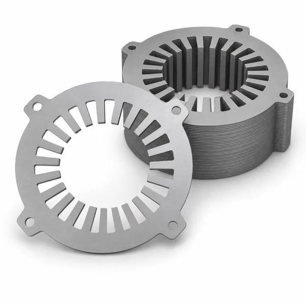
01 STATOR COMPONENTS
Stator laminations & cores
Precision stamped stator laminations and finished laminated stator cores for motor manufacturers. Discuss geometry, material, insulation and core construction with our team.
02 ROTOR COMPONENTS
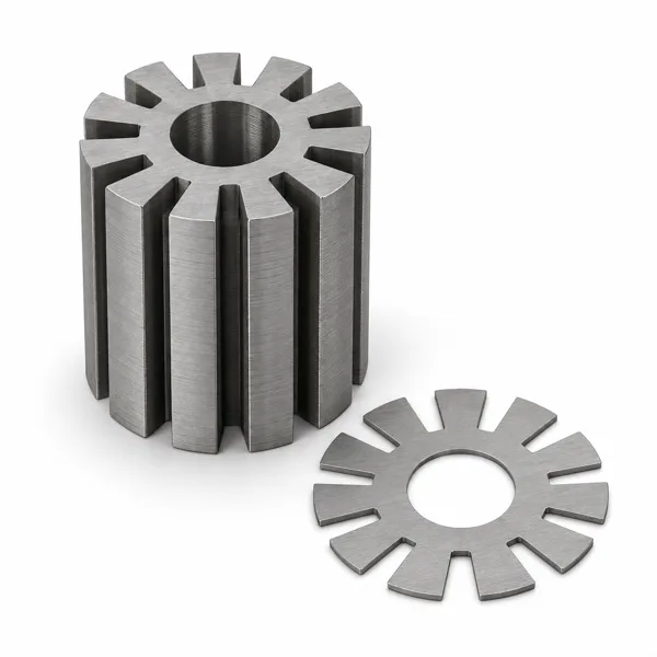
Rotor laminations & cores
Rotor laminations and finished laminated rotor cores made to project drawings. Matching and construction requirements can be reviewed with the stator design.
03 MATCHED COMPONENTS
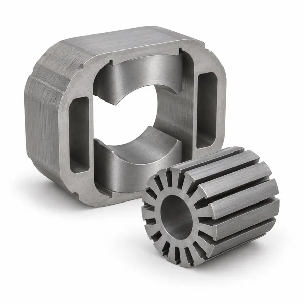
Matched stator–rotor sets
Coordinate matching laminations or finished cores as a single motor program, with sample and inspection criteria agreed before production.
04 PRECISION METAL PARTS
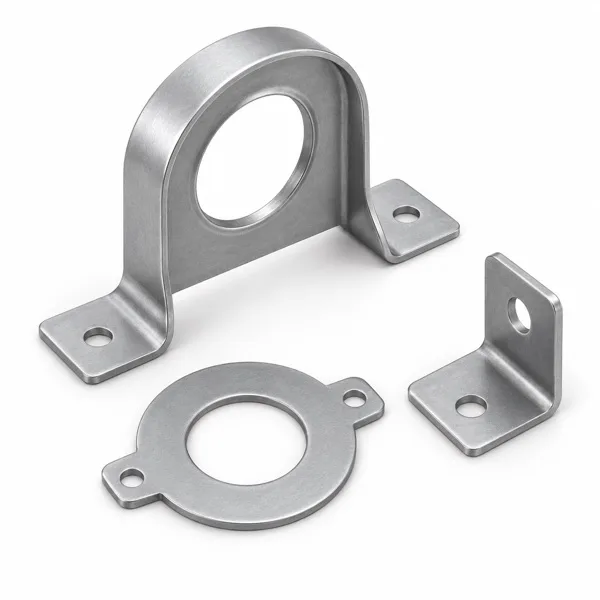
Motor brackets & stamped parts
Project-specific metal brackets and accessories. Suitability depends on drawings, material and production requirements.
Product series
Browse component series by motor type. Dimensions, materials and supply scope are confirmed from your project drawing.
Illustrations show typical component structures, not Minfai product photographs. Actual geometry follows the project drawing.
Universal Motor Stator & Rotor CoresStator and rotor laminations and laminated cores for universal motor projects.Explore series →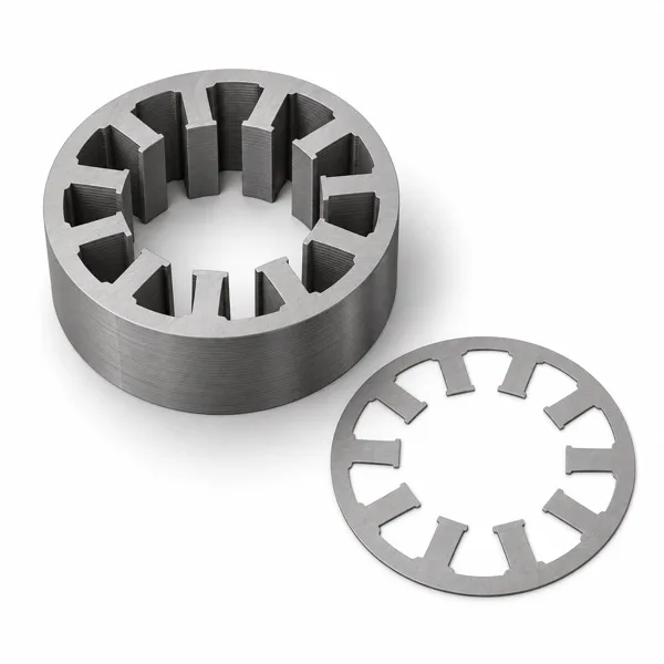 Brushless Motor CoresDiscuss stator and rotor core requirements for a brushless motor design.Explore series →
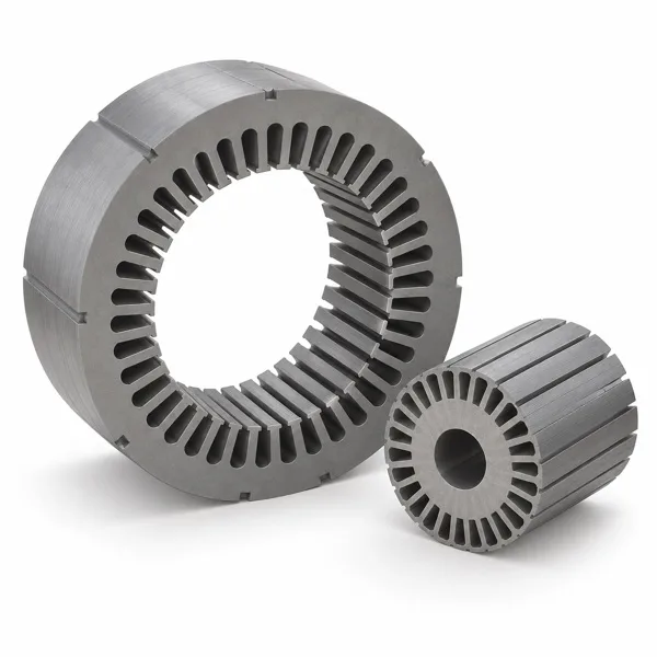 Induction Motor CoresReview stator and rotor laminations or finished cores for an induction motor project.Explore series →
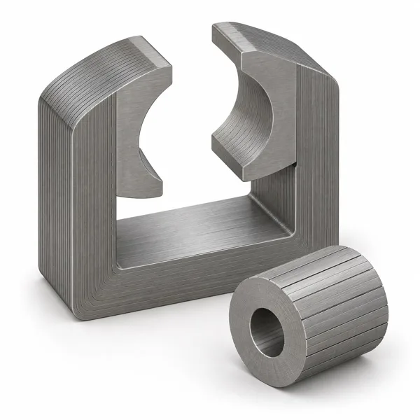 U-Frame Motor CoresDiscuss the core geometry and component scope for a U-frame motor design.Explore series →
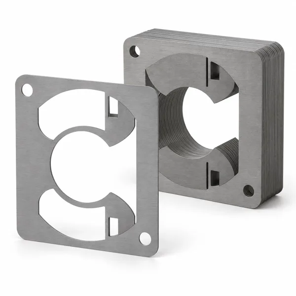 Shaded-Pole Motor CoresReview stamped laminations and core construction for a shaded-pole motor project.Explore series →
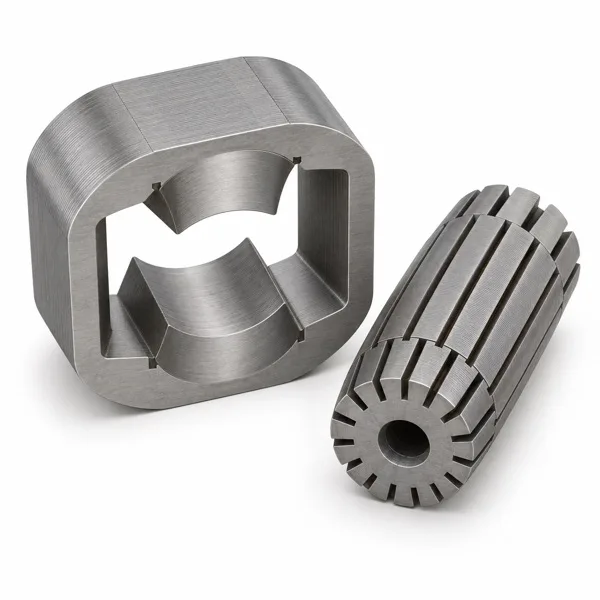 Hand Mixer Motor CoresDiscuss motor core components for a hand mixer application from your current drawing.Explore series →
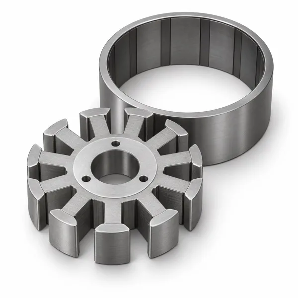 Outer-Rotor Motor CoresReview the stator and outer-rotor component arrangement for your motor design.Explore series →AC Motor CoresDiscuss laminations and laminated core requirements for an AC motor project.Explore series →DC Motor CoresDiscuss laminations and laminated core requirements for a DC motor project.Explore series →Motor Brackets & AccessoriesProject-specific motor brackets and precision stamped metal accessories.Explore series →
How to choose a motor lamination or core category
Choose by the part being purchased first, then use the motor series to explain the application. Stator laminations and cores describe the stationary magnetic component; rotor laminations and cores describe the corresponding rotating component. Matched sets coordinate the two drawings. Brackets and stamped parts cover mechanical fixing and support requirements.
Motor family names are useful for routing an inquiry, but they are not fixed dimension codes. A universal motor, an induction motor and a brushless motor may require different lamination layouts, even when the finished motor has a similar overall size. Refer to the specific series page and attach the drawing for the exact part you want quoted.
For electrical steel laminations, material grade, sheet thickness and any specified interlaminar insulation are part of the drawing requirements. A stack order also needs the required stack height, joining or fixing scope and acceptance method. Current material options, tooling suitability and order terms are reviewed before quotation; photographs do not establish stock availability.
Questions before component procurement
Can one motor project use more than one product category?
Yes. A project may include separate stator, rotor and bracket drawings. List each part with its required supply form and quantity, then identify the assembly relationships that need coordinated sample review.
What is the difference between a lamination drawing and a core drawing?
The lamination drawing defines the stamped sheet. A core or stack drawing also defines the assembled stack, including axial dimensions and relevant construction or inspection requirements. Provide both when needed.