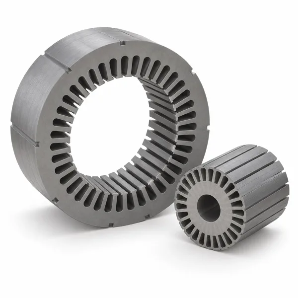
Stator laminations
Review profile, slots, material thickness and stacking requirements against the motor design.

From stator and rotor laminations to motor brackets, your drawing guides engineering review, tooling development and stamping production.
COMPONENT SCOPE
Source individual laminations or discuss finished laminated cores for your project. Images illustrate typical structures; the approved drawing defines the part.
Review profile, slots, material thickness and stacking requirements against the motor design.
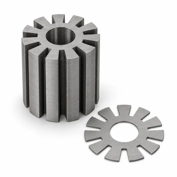
Discuss rotor outside diameter, shaft bore, slots and mating requirements.
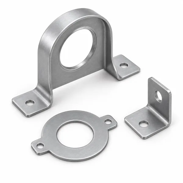
Assess bracket and metal-part materials, geometry and secondary operations from the drawing.
ENGINEERING & TOOLING
Connect engineering review, tooling and samples so both teams align requirements before production.
Review profiles, critical tolerances, material and assembly requirements before committing to a production approach.
Plan tooling around part geometry, volume and inspection needs, followed by manufacture, assembly and die trials.
Use samples to review dimensions and supply form. Define stacking, surface treatment or other secondary operations in the quotation where required.
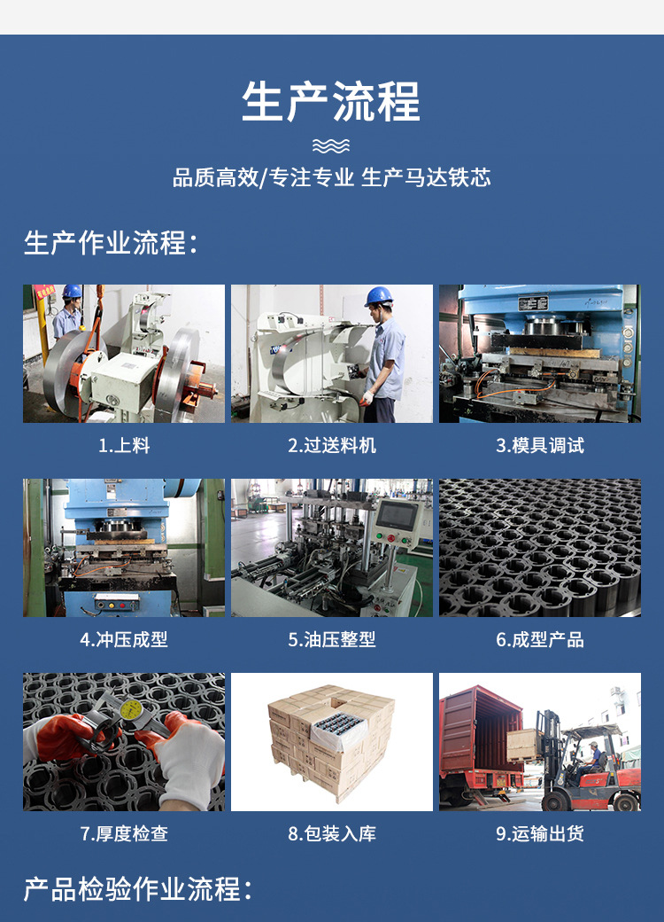
PROJECT PROCESS
Agree the scope and approval requirements at each stage. Payment arrangements follow the quotation and mutual agreement.
Share CAD, PDF, 3D data or part photographs with material, quantity and timing.
Confirm process and supply scope, then discuss tooling cost, unit price, minimum quantity and lead time.
After technical and commercial agreement, arrange die design, manufacture and trials.
Submit agreed samples and inspection information for customer testing and approval.
Produce, inspect, pack and deliver to the approved drawings and samples.
QUALITY CHECKS
Agree inspection methods and tolerances during drawing and sample review.
Confirm material grade, thickness and required material properties.
Agree critical dimensions, hole positions, mating tolerances and burr requirements from the drawing.
Align sample standards, inspection points and required records.
Precision metal stamping starts from a controlled part drawing. For motor laminations, the profile, material and sheet thickness establish the blank to be produced; finished stacks add construction requirements. Brackets and other formed pieces also need bend, hole and locating references that explain how the finished part fits the assembly.
Tooling review should connect the functional features of the component with the intended sample and production quantities. Discuss which dimensions are checked on the loose stamped part and which are checked after stacking or forming. If additional finishing or assembly operations are requested, list them separately so tooling and production quotations remain comparable.
Before releasing a drawing for production, confirm the revision, material, measurable acceptance points and sample identity. Agree packing that protects stamped edges and finished part geometry. Any specific process limits, surface requirements or supporting records are confirmed with the project quotation and technical review.
Yes, but each part needs its own drawing and material requirements. Magnetic core components and mechanical supports serve different functions, so list their quantities, supply stages and acceptance points separately.
Agree the drawing revision, material, functional dimensions, sample approval requirements and expected production scope. Tooling and commercial terms should be stated in the quotation or project agreement.
Prepare a drawing or part description, material, quantity and target timing. We can arrange drawing exchange after initial contact.